Big Red is Looking for more
Fuel!
Programable
EFI & Ignition
System: Supercharger, Home, End Result
|
Big Red is Looking for more
Fuel! |
|
| If more air (and therefore O2) is
being forced into the combustion chamber, more fuel has
to be added and the air to fuel ratio has to be
dynamically maintained near stochimteric 14.7. Higher and
the "lean" condition will create too high
chamber temperatures causing premature failure. Too low
and the "rich" mixture wastes fuel, carbons
everything up and simply lowers performance. Therfore, I wanted to switch from a carb based induction system (which tries to control mixture mechanically which has difficulty handling a great amount of variability) to programable fuel injection which uses sensors and a computer chip to adust the ratio dynamically as conditions change. Since I was also intending to add boost, I wanted programable timing to be able to easily retard the timing at higher boosts. For this I looked to Racetech and their SDS (Simple Digital System) 6F system. I would however, have to create a custom manifold to hold the injectors and the fuel rail as well as accept the compressed, cooled air from the supercharger. A high pressure fuel system is a must and sensors have to be mounted in their appropriate locations. |
  |
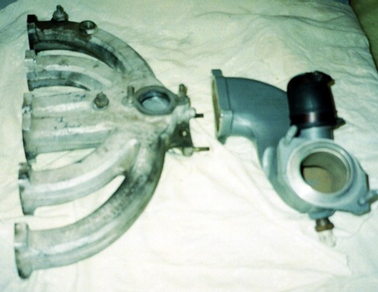 1.0 Aluminum single barrel needs to be connected to the T-bird aluminum inlet tube. This dimension determined by blower (right) and battery (left) clearances. |
 1.1 First cut the end off the manifold, the raised carb mounting boss and the EGR boss on the inside. Set back cut so that manifold opening exposed equals inner dimensions (3.75" x 1.375" of rectangular inlet tube.  |
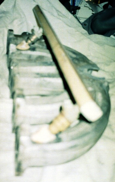
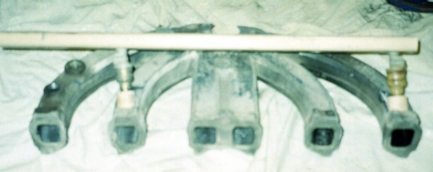 1.2 Its time to get an idea as to where the fuel rail will go. Two scrap injectors countersunk into a hockey stick along with wooden bungs all held together with hot melt. Space reserved! |
 |
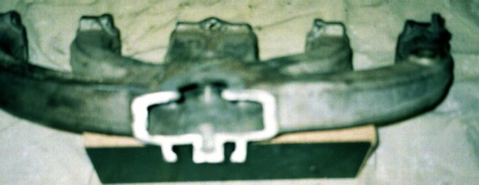
NOTE: I made the mistake of cutting off the entire end and later had to weld it back on. If you intent to use stock exhaust manifolds or Dutra Duals like I am, you need to retain the bottom portion of the manifold which matches up with the exhaust. Therefore, cut down to the floor of the intake manifold and then cut horizontally. | |
1.3 I had the machining and TIG welding done by a local firm called Aerotech. 1.4 Right - Injector bung detail: on the fly changes were made. Example: higher bung position required 'porting' of the manifold so as not to constrain the spray. |
 |
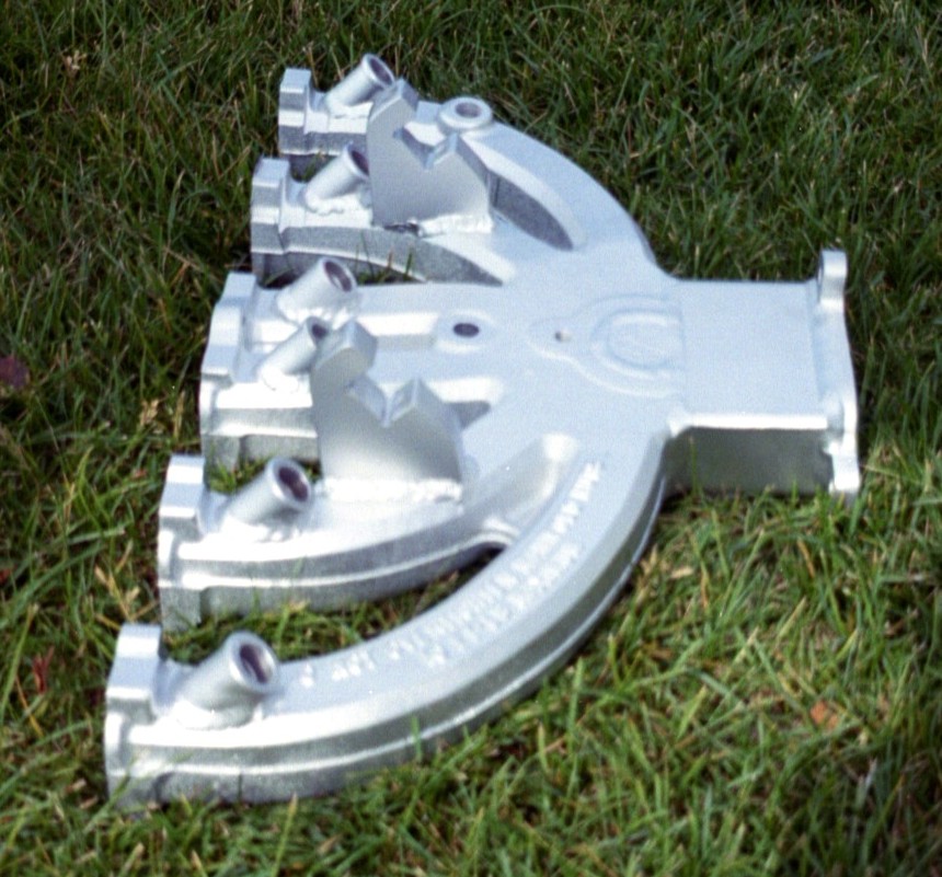
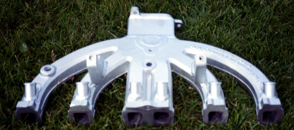
 1.4 Finished manifold: bottom view. The exhuast mating surface has been reattached. The holed are now threaded as well with 7/16" UNC for new bolts from the exhaust manifold to attach to. |
|
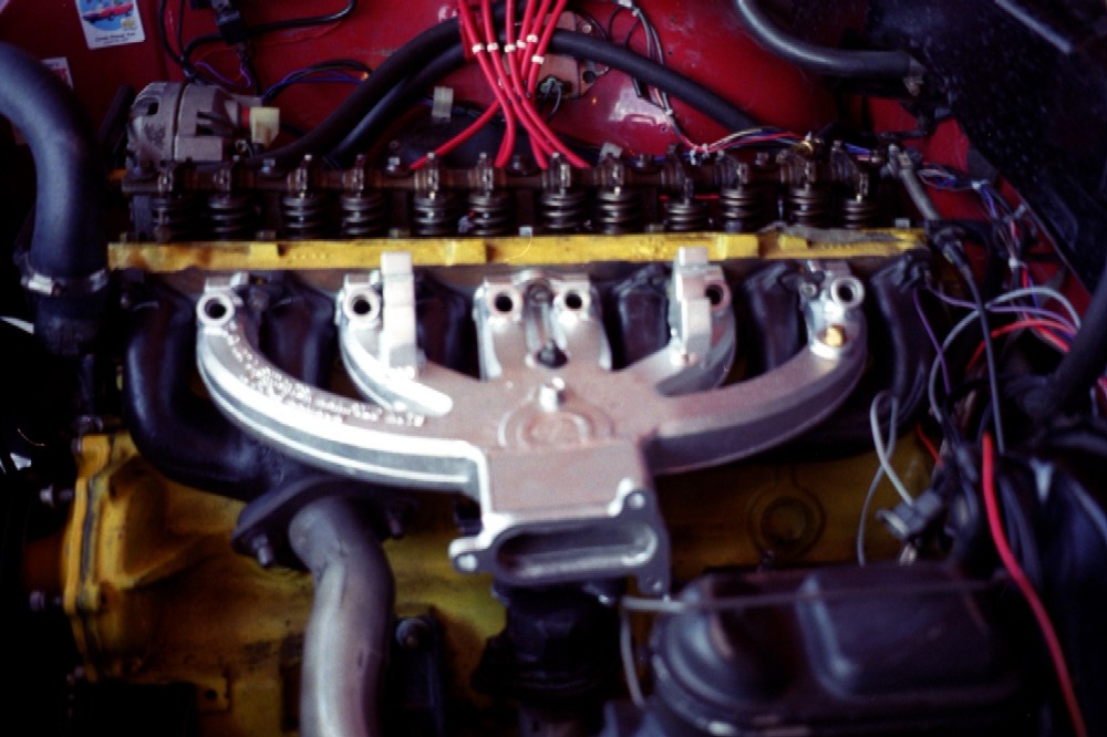
| INTAKE
MANIFOLD This is the part that added complexity to the project. Customizations were required for both the EFI and supercharger aspects. Since I was tight for time, I made all the changes at the same time.
|
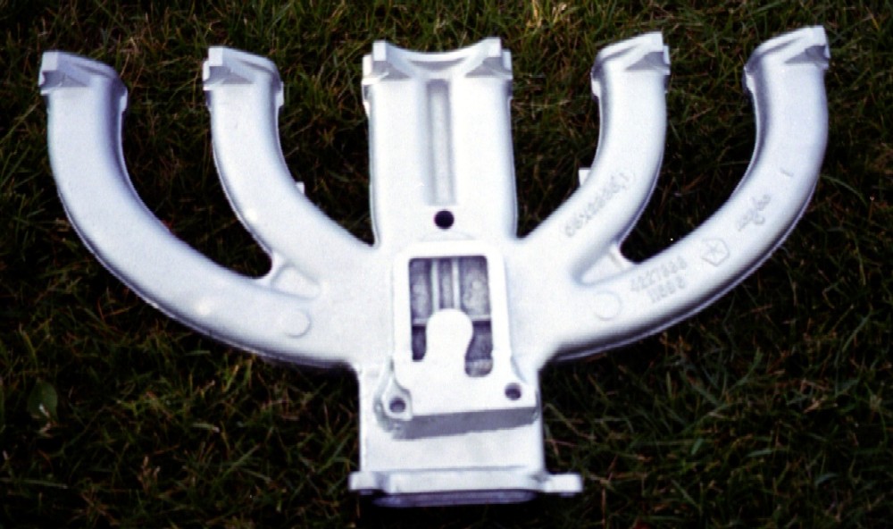
 1.5 Finished manifold: front view. I finished it off with a high temp aluminum paint and baked it at 350' for 3 hours. (PS: Its okay, Marilou will not be reading the details!) |
 1.6 Finished manifold: head view - note the lateral positioning of fuel rail supports
|
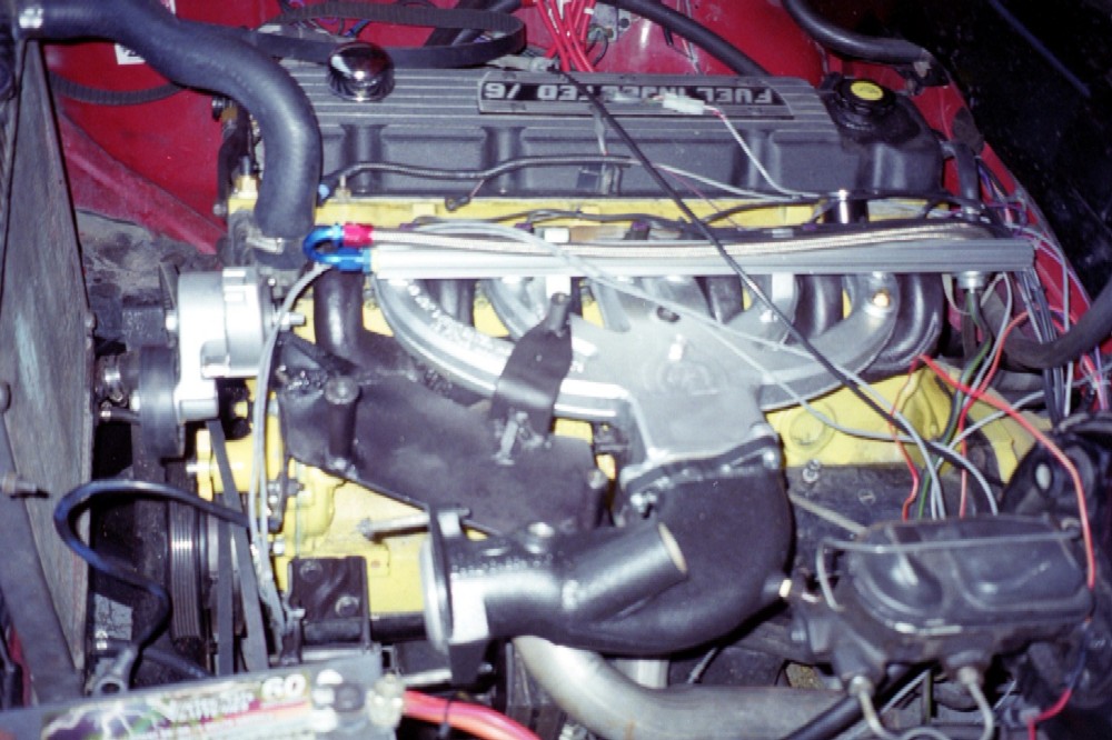
 1.8 Finished manifold: Another pic with fuel rail mounted and inlet elbow from intercooler. |
| AIR INLET I needed to build something custom to match the space available. This turned out to be relatively straightforward.
|
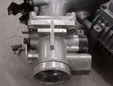 2.0 Here's the stock throttle body off the '90 T-bird Supercoupe. |
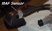 2.1 Since I'm using a speed density system (MAP) instead of the factory MAF(Mass Air Flow), I will not need this venturie style sensor. |
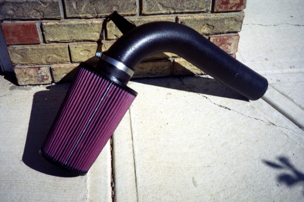
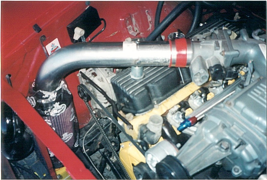 2.2 3" mandrel bent tubing with a support bracket off to fender bolt. K&N filter element with textured black 'truck bed liner paint'! |
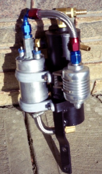
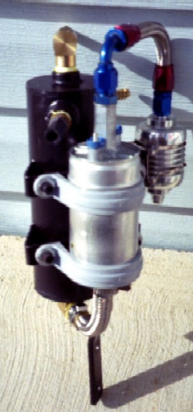
| FUEL SYSTEM The SDS people
recommend the instalation of a surge tank to ensure that
the high pressure pump stays wet on cornering. This
eliminates the need for custom fuel tank work and some
high pressure lines. Spent some extra bucks on Earl's
fittings and steel braid hose. Now my finger tips look
like gramother's pin cushion! |
 3.0 High level schematic diagram for fuel system 3.1 High
level routing and parts used for fuel system |
|
 3.4 Here's some detail on mounting the fuel system.
|
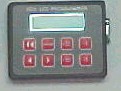
| ECU
(Engine Control Unit) SYSTEM I purchased the SDS 6F system from Racetech. This provides for programable fuel and ignition timing based on conditions. They were very helpful. More to come here as I take more pics.
The EFI system to be installed here will be a speed density system which adjusts the parameters not based on measuring airflow but rather on the differential between manifold absolute pressure and atmospheric. |
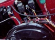
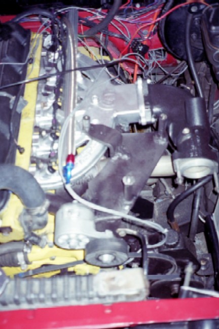
4.0 Gone are the electronic ignition
unit, ballast resistors, coil, distributor and associated
wiring. In there place are the: ECU (left), a GM coil
pack, sensors (air temp, engine coolant temp, crank
position magnets, manifold pressure and O2), 4 relays and
the associated wiring.
4.1 Relays on firewall: fast idle, injectors & coils, fuel pump & start. |
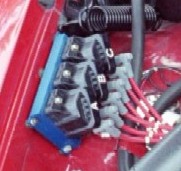 4.2 The coil pack and MSD wires.
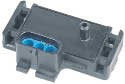
4.3 The 2 bar MAP (Manifold Air Pressure) hooks up between the intercooler and the intake manifold. |
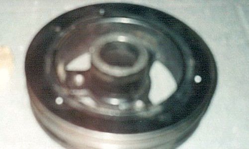 4.4 There are 4 magnets in the back side of the pulley (early 80's truck). 3 are spaced 120' from each other with the 4th, the synch magnet being 40' off of a timing magnet. Pic is poor but look for the white spots.
|
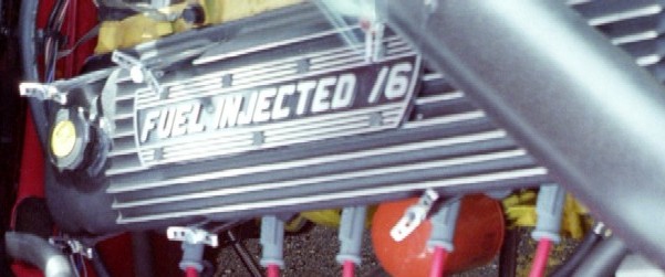
| VALVE COVER Now I can display the plaque with pride!
|
5.0 I started with a Clifford cover. I soon found the root cause of my former oil leaks. As cast, the extra material around the bolt holes 'bottomed out' on the head bolt corners before the gasket was squeezed. Required Dremel & grinder work! Not good!! | 5.1
Plaque BEFORE: Ford 3.8L 90 engine - Got to get rid of the one side of the "V"!
|
5.2
Oil filler cap Since the inlet tube runs over top of the filler hole, I converted the former PCV hole with the addition of the neck & cap from a late 80's Ford Kia?? |
| EXHAUST No significant change to dual exhaust |
1.0 No choke so I was able to grind off the old choke stove pipe on the exhaust manifold | 1.1 I mounted my O2 sensor in the pipe coming from the front 3 cylinders. |